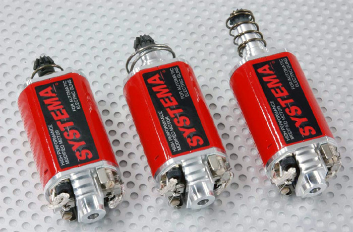
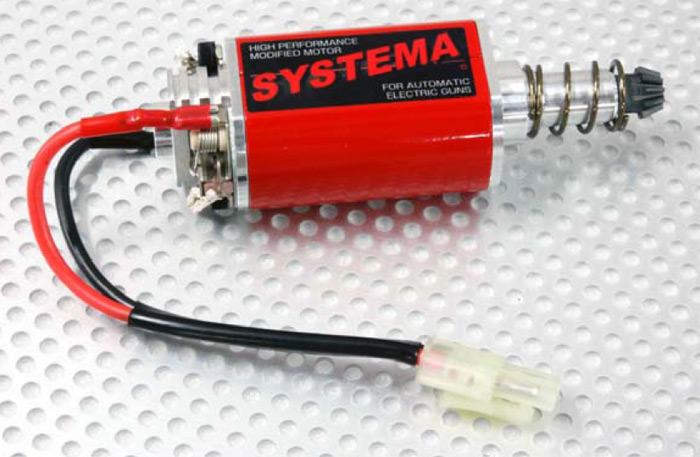
Systema "A to Z" AEG Motor Released
OptimusPrime
14 Oct 2010
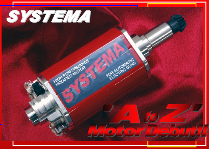
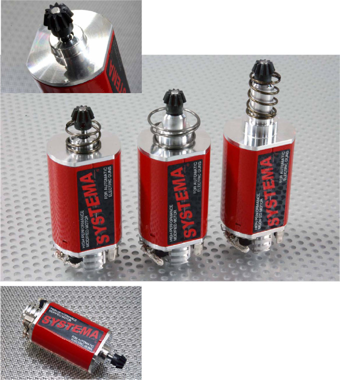
Another new motor with some interesting innovations now released by Systema Engineering... "By uniting the already popular TURBO and MAGNUM motors we have developed the New A to Z Motor set for release. The theme for our new product is: Improvement of torque through rotary balance. With the adoption of theNeodymium Magnet an unsurpassed amount of torque is generated for the MAGNUM Motor. Even ourCMB (which has the M170 Spring built in), has performed marvelously to fully satisfy many of our customers. On the other hand, the purpose of the TURBO Motor (which uses a Wet Magnet) is to focus on motor spin, by utilizing a hand wound high balanced rotor, this ensures an extreme rotor spin which at thesame time produces torque as well. Simply by changing out the stock motor, we have fascinated many of ourfans by making the performance of the High Speed Tuning possible.
On the basis of our results, and with the collection and integration of what we considered to be two completely different paths of performance we came up with our “A to Z” Motor.
To sum up the goal in performance of this new motor in one sentence, it would be: The acquisition of the highest possible revolutions along with the highest level of torque.
To make this theme a reality, we reviewed the production method of each and every single part, focusing on the actual parts that rotate and the support structure surrounding the rotating parts, even the most basic of part has been greatly reviewed. Therefore, we would like to give specific explanation below, of the production method into each part.
New Production Rotor
The biggest change of our New A to Z Motor is our newly designed Rotor. When producing therotor, the “core piece” is considered the mostdifficult part to create as it is used to maintain thebalance while the motor is spinning. The core piece is made of a press fit die (which is described as non-stacking) using a preset number of sheets layered together thus producing a part that is already balanced.
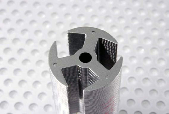
After installing all of the other components, there is hardly any work involved in fine tuning during the final balancing process, as the level of precision in each part makes the work practically unnecessary. Naturally, the precision of the hole of the core piece along with the layering process is so well made that inserting the Rotor Shaft shows no distortions so that there are no obstructions to the shaft. With this manufacturing method, each core piece is punched out and manually repeated, this general method of manufacture once completed (regardless of it marked difference in precision), is typically not adopted due to cost relatedissues. However, this method is preferred particularly when a high number of revolutions is sought after for a small sized motor.
The degree of concentricity between both ends of the Rotor
We secured the precision through the production method of the Rotor. Next, we seek to pursue the revolution balance of the motor; in other words, the level of concentricity to where both ends of the rotor was set into place. The structure of the conventional motor, which is the motor case (motor can) has generally been produced via press fit processing. The reason why this method of production is typicallychosen in many cases is because of its productivity improvement through its superior cost saving aspect.
If the product was a simple circular design it would be easy to create a consistent and precise product due to the die production technology, however in the case of an AEG motor it requires a variant of shapes; the dimensions from the external forms of the finished product needs correction, along with creating the mold ofwhere the bearing is installed (from the side of the Motor Pinion side of the drive shaft), we were not able to make anything that was satisfactory.
Therefore this time we created a structure where we could maintain a high level of concentricity between both ends by using a precision cutting process we created a pipe form case, then we inserted both thefoundation of where the bearing is installed that directly supports the Rotor (End Bell) as well as with our newly designed Motor Bushing. Furthermore, the case is a two pieces structure using the same die production method to create the parts for both sides allotting a Dove-tail groove to combine the two pieces, which ensures an even combination.
Rotary Mass
The bigger the mass of the object that rotates, so too is the torque that is produced. However, limitations on size as well as certain number of revolutions could pose a bad influence on the motor and may complicate things. Hence, in the newly designed Rotor, we maintained the outer dimension of the core piece while adding mass by adequately lengthening it. With this technique, it extends the length of the winding coil,thereby generating greater torque. For the improvement of performance “we’ll do everything we can”. This is an example of our attitude towards the production of our products.
Bearing supporting two points
Conventionally (particularly for long type versions), a maximum of 4 Ball Bearings were used; however we decided to switch to a Two Bearing support (for all of our models) to reduce any unnecessary load resistance. At the same time, the setting of the power side Bearing is optimized by positioning it as close as possible to the Pinion Gear; in doing so, even during the peak of maximum torque, the oscillation of the shaft is extremely minimal.
Silent Sound / The process of breaking in the Motor
Rather than installing the Motor right after purchase, we highly recommend to break in the Motor prior to setting it into the chassis. The effect of breaking in the Motor familiarizes theCarbon Brush with the Commutator, and rather than abruptly running the Motor through the completed Mech Box, which puts an unnecessary load (possibly damaging the Bearing); this important step of breaking in the Motor will allow the use of the Motor comfortably for a long time.
To achieve the desired results, the process is by contrast extremely simple:
- Prepare two cords approximately 100mm each, on one cord install a battery type socket (male plug).
With the other cord, peel off about 5mm of the outerlayer (exposing the wire), then affix it onto the Brush Spring area. - Set the Motor onto a vice to restrict movement, connect the socket onto a battery. (New Motors spin with great force.This is very dangerous, therefore do not attempt to hold theMotor while doing this procedure.)
- It is recommended to use a low voltage battery (such as an8.4V), as well as low capacity (such as a mini-type). If using alarge type battery, its fine to use a battery that is on theverge of losing all of its charge.
- It is ideal to run the Motor for about 4 to 5 minutes. After running the Motor please be careful in handling it as itwould be very hot.
For those who wish for an even more efficient Motor, remove the Carbon Brush and put one drop of water onto the Commutator prior to doing this procedure. Due to the surprisingly high consumption rate of the Carbon Brush as it reacts to water; the shape of the Brush to the Commutator conforms that much quicker.
Although sold separately, we have prepared the cord used to break in the Motor. Acclimating the Motor is easily accomplished by simply connecting the cords as instructed above.
While breaking in the new Motor, very little noise will benoticed; it is that quiet running Motor we are convinced that you will understand our company’s effort to produce this high quality product.
In Conclusion
We had a strong desire to put all of the best of our production technology into our Motor. The deep crimson finish on the outer appearance of our new Motor, makes a clear distinction from our previous models. Furthermore, we hope you will understand that this is by far the strongest specs in the history of the AEG Motor."